Chapter 4

Optical Mirage

William Viezee


1. Introduction
2. Cross Section of Surveyed Literature
3. Basic Physical Concepts and Atmospheric Variables Involved in Light Refraction
4. Visual Characteristics of Light-Refraction Phenomena in the Cloud-Free Atmosphere
5. Evaluation of the State-of-the-Art Knowledge
6. Conclusions
# BIBLIOGRAPHY


BACK to Section VI Index | BACK to Contents Page


1. Introduction

An optical mirage is a phenomenon associated with the refraction of light in the gaseous (cloud-free) atmosphere. During mirage a visible image of some distant object is made to appear displaced from the true position of the object. The image is produced when the light energy emanating from the distant source travels along a curvilinear instead of a rectilinear path, the curvilinear path, in turn, arises from abnormal spatial variations in density that are invariably associated with abnormal temperature gradients.

The visible image of the mirage can represent shape and color of the "mirrored" object either exactly or distorted. Distortions most commonly consist of an exaggerated elongation, an exaggerated broadening, or a complete or partial inversion of the object shape. Frequently, mirages involve multiple images of a single source. Under special conditions, refractive separation of the color components of white light can enhance the observation of a mirage. Atmospheric scintillation can introduce rapid variations in position, brightness, and color variations of the image.

When both the observer and the source are stationary, a mirage can be observed for several hours. However, when either one or both are in motion, a mirage image may appear for a duration of only seconds or minutes.

Although men have observed mirages since the beginning of recorded history, extensive studies of the phenomenon did not begin till the last part of the 18th century. Since that time, however, a large volume of literature has become available from which emerges a clear picture of the nature of the mirage.

The comprehensive body of information presented here is based on a survey of the literature, and constitutes the state-of-the-art knowledge on optical mirages. The report provides a ready source of up-to-date information that can be applied to problems involving optical mirages.

[[987]]


No claim is made that all existing pertinent writings have been collected and read. The contents of many publications, especially of those dating back to the last part of the 18th Century and the beginning of the 19th Century are evaluated from available summaries and historical reviews. Also, when a particular aspect of the mirage phenomenon is considered, the collection of pertinent literature is discontinued at the point where the state-of-the-art knowledge appears clearly defined. The collected volume of literature covers the period 1796 to 1967.

In essence, the literature survey yields the following principal characteristics of the mirage:

  1. Mirages are associated with anomalous temperature gradients in the atmosphere.

  2. Mirage images are observed almost exclusively at small angles above or below the horizontal plane of view; mirages, therefore, require terrain and meteorological conditions that provide extended horizontal visibility.

  3. A mirage can involve the simultaneous occurrence of more than one image of the "mirrored" object; the images can have grossly distorted forms and unusual coloring.

  4. Extreme brightening and apparent rapid movement of the mirage image in and near the horizontal plane can result from the effects of focussing and interference of wavefronts in selected areas of the refracting layer.

Only minor shortcomings appear to be evident in present knowledge of mirage phenomena. Ultimately, a unified theory is desirable that can deal with both the macroscopic and microscopic aspects. Currently, the behavior of light refraction on a large scale is represented by means of rays while the finer details are treated with the wave theory. More observations are needed that deal with the microscopic optical effects of the mirage. The finer details that arise mostly from focussing and interference are not commonly observed. They require close examination of areas that are highly selective in time and place.

BACK To Top


2. Cross Section of Surveyed Literature

The contents of this report are based on a survey of literature on atmospheric refraction in general and on optical mirages in particular. The survey began with the review of such basic sources of information on atmospheric optics as Meteorologische Optik, by Pernter and Exner, Physics of the Air, by Humphreys, The Nature of Light and Colour in the Open Air,

[[988]]


by Minnaert, and The Compendium of Meteorology. These sources present historical summaries, and their contents are to a large extent based on literature surveys. Key references mentioned in these sources were examined and a large volume of literature was subsequently collected by following successive reference leads. Pertinent information on atmospheric scintillation was obtained from several sources, in particular from Optical Scintillation; A Survey of the Literature, by J. R. Meyer-Arendt. A cross section of the collected literature is listed below. Because of the wide range of aspects covered, the literature is listed in the following categories:

  1. papers on optical mirage the contents of which are mostly descriptive,

  2. papers that propose theoretical models of spheric refraction or optical mirage,

  3. papers that compare theory and observation,

  4. papers that are concerned with the application of terrestrial light refraction to meteorology, surveying, and hydrography,

  5. papers that present average values of terrestrial refraction based on climatology, and

  6. papers on atmospheric scintillation.

Within each category, publications are arranged chronologically.

In category 1, descriptive accounts of mirages go back in time to 1796, when Joseph Huddart observed superior mirages near Macao. (Earlier accounts can be found in Meteorologische Optik.) Numerous recent observations of abnormal atmospheric refraction can be found in The Marine Observer. The two "classical" observations most frequently quoted as having "triggered" a long series of investigations on optical mirage are the observations of Vince and Scoresby. Vince (1798) from a position on the sea shore observed multiple images of ships, some upright and some inverted, above the ocean horizon; Scoresby (1820) observed elevated images of ships and coastal lines while navigating near Greenland. Both observations were carefully documented and results were read before bodies of the Royal Society.

Proposed theories of the mirage (category 2) are basically of three types, that are best represented by the respective works of Tait (1883), Wegener (1918), and Sir C. V. Raman (1959). Tait (in his efforts to explain the observations by Vince and Scoresby) considers a vertically

[[989]]


finite refracting layer having a continuous change in refractive index, and formulates the ray paths for a plane-stratified atmosphere. Wegener (motivated by mirage observations made during his stay in Greenland) replaces Tait's finite refraction layer with a "reflecting" surface - i.e. a surface of discontinuity in the refractive index - and formulates the ray paths for a spherically stratified atmosphere. Raman questions the use of geometric optics in the theory of the mirage and shows by means of physical optics that the upper boundary of the refracting layer resembles a caustic surface in the vicinity of which focussing and interference are the major mirage-producing effects. All three theories quite accurately describe various mirage observations.

Comparisons made between observation and theory (category 3) indicate that the two are compatible - i.e., abnormal light-refraction phenomena are associated with anomalous atmospheric-temperature structure. Many investigations (category 4) are concerned with determining the effects of light refraction on optical measurements made in such fields as surveying and hydrography. Corrections for refraction based on average atmospheric conditions have been computed (category 5). Of specific interest to meteorologists are the attempts to develop inversion techniques for obtaining low-level temperature structure from light-refraction measurements (category 4). The temperature profiles that can be obtained do not have the desired resolution and accuracy. During the last decade, literature on atmospheric scintillation has become extensive due to its importance to astronomy, optical communication, and optical ranging. A selected number of recent papers are presented in category 6.

The publications categorized below represent a cross section of the various endeavors that have resulted from the Earth's atmosphere having light-refraction properties. The body of information is fundamental to the contents of this report. In addition to the listed literature, many other sources of information on atmospheric optics were consulted in its production. They are referenced throughout the text, and are compiled in a bibliography at the end of the report.


CATEGORIES
1. Descriptive
2. Theoretical Models
3. Theory vs. Observation
4. Application
5. Average values
6. Atmospheric Scintillation
 
BACK TO SECTION 2


[[990]]


Category 1

(Descriptive Accounts)

  1. Huddart, Joseph, "Observations on Horizontal Refractions Which Affect the Appearance of Terrestrial Objects, and the Dip, or Depression of the Horizon of the Sea," Phil. Trans. Vol. 87, pp. 29-42 (1797).

  2. Vince, S., "Observations on an Unusual Horizontal Refraction of the Air; with Remarks on the Variations to Which the Lower Parts of the Atmosphere are Sometimes Subject," London Phil. Trans., Part 1, pp. 436-441 (1799).

  3. Wollaston, William Hyde, "On Double Images Caused by Atmospheric Refraction," Phil. Trans., Vol. 90, pp. 239-254 (1800).

  4. Scoresby, William, "Description of Some Remarkable Atmospheric Reflections and Refractions, Observed in the Greenland Sea," Trans. Roy. Soc. Edinburgh, Vol. 9, pp. 299-305 (1823).

  5. Parnell, John, "On a Mirage in the English Channel," Phil. Mag., Vol. 37, pp. 400-401 (1869).

  6. Forel, F. A., "The Fata Morgana," Proc. Roy. Soc. Edinburgh, Vol. 32, pp. 175-182 (1911).

  7. Hillers, Wilhelm, "Photographische Aufnahmen einer mehrfachen Luftspiegelung," Physik. Zeitschr., Vol. 14, pp. 718-719 (1913).

  8. Hillers, Wilhelm, "Einige experimentelle Beitr~ge Zum Phanomen der dreifachen Luftspiegelung nach Vince," Physikalische Zeitschrift, Vol. 15, p. 304 (1914).

  9. Visser, S. W. and J. Th. Verstelle, "Groene Straal en Kimduiking," Hemel en Dampkring, Vol. 32, No. 3, pp. 81-87 (March 1934).

  10. Meyer, Rudolf, "Der grUne Strahl," Meteorologische Zeitschrift, Vol. 56, pp. 342-346 (September 1939).

  11. Science Service, "Mirage in Desert May Explain How Israelites Crossed Red Sea Unharmed," Bull. Am. Met. Soc., Vol. 28, p. 186 (1947).

[[991]]


  1. Ives, Ronald L., "Meteorological Conditions Accompanying Mirages in the Salt Lake Desert," J. Franklin Institute, Vol. 245, No. 6, pp. 457-473 (June 1948).

  2. St. Amand, Pierre and Harold Cronin, "Atmospheric Refraction at College, Alaska, During the Winter 1947-1948," Trans. Am. Geophys. Un., Vol. 31, No. 2, Part 1, (April 1950).

  3. Ten Kate, H., "Luftspiegelungen," Hemel en Dampkring, Vol. 49, No. 5, pp. 91-94 (1951).

  4. Ewan, D., "Abnormal Refraction of Coast of Portugal," The Marine Observer, Vol. 21, No. 152, p. 80 (April 1951).

  5. Mitchell, G.E., "Mirage in Gulf of Cadiz," The Marine Observer, Vol. 21, No. 152, p. 81 (April 1951).

  6. Illingsworth, J., "Abnormal Refraction in the Gulf of St. Lawrence," The Marine Observer, Vol. 22, No. 156, pp. 63-64 (April 1952).

  7. Markgraf, H., "Fata Morgana an der Norseekuste," Wetterlotse, Vol. 47, pp. 200-204 (November 1952).

  8. Ten Kate, H., "Fata Morgana," Hemel en Dampkring, Vol. 50, No. 2, pp. 32-34 (1952).

  9. Heybrock, W., "Luftspiegelungen in Marokko," Meteorologische Rundschau, Vol. 6, No. 1/2, pp. 24-25 (January/February 1953).

  10. Ruck, F.W.M., "Mirages at London Airport," Weather, Vol. 8, No. 1, pp. 31-32 (January 1953).

  11. Ainsworth, P.P., "Abnormal Refraction in Cabot Strait, Gulf of St. Lawrence," The Marine Observer, Vol. 23, No. 160, pp. 77-78 (April 1953).

  12. Kebblewhite, Alexander W. and W. J. Gibbs, "Unusual Phenomenon Observed from East Sale," Australian Meteorol. Mag., Melbourne, No. 4, pp. 32-34 (August 1953).

  13. Menzel, Donald H., "Lenses of Air," Chapter 16 of Flying Saucers (Harvard Univ. Press, Cambridge, Mass., 1953).

  14. Nelson, Robert T., "Mirages and Chlorophyll." Better Farming, (Summer 1953).

[[992]]


  1. Richard, R., "Phenomene Optique Remarquable," La Meteorologie, 4th Ser., No. 32, pp. 301-302 (October/December 1953).

  2. Vassy, E., "Quelques Remarques sur un Phenomene de Mirage du Disque Solaire," La Meteorologie, 4th Ser. No. 32, pp. 302-303,(October/December 1953).

  3. Williams, A. E., "Abnormal Refraction in North Atlantic Ocean," The Marine Observer, No. 166, pp. 208-210 (October 1954).

  4. Jezek, ___ and Milan Koldovsky, "Totalni reflexe na inversnich vrstvach pozorovana s Milesovsky dne 18, listopadu 1953," Meteorologicke Zpravy (Prague), Vol. 7, No. 1, pp. 11-12 (February 1954).

  5. Baines, J. P. E., "Abnormal Refraction off Cape Town," The Marine Observer, Vol. 25, No. 167, pp. 31-34 (January 1955).

  6. Ashinore, S. E., "A North Wales Road Mirage," Weather, Vol. 10, pp. 336-342 (1955).

  7. Ballantyne, J., "Abnormal Refraction in North Atlantic Ocean," The Marine Observer, Vol. 26, No. 172, pp. 82-84 (April 1956).

  8. Durst, C. S. and G. A. Bull, "An Unusual Refraction Phenomenon seen from a High-Flying Aircraft," Meteorological Magazine, Vol. 85, No. 1010, pp. 237-242 (August 1956).

  9. Collin, P., "Abnormal Refraction in Gulf of Aden," The Marine Observer, Vol. 26, No. 174, pp. 201-202 (October 1956).

  10. Baker, R. E., "Abnormal Refraction in Red Sea," The Marine Observer, Vol. 27, No. 175, pp. 12-15 (January 1957).

  11. Gabler, Horst, "Beobachtung einer Luftspiegelung nach oben," Zeitschrift fur Meteorologie (Berlin), Vol. 12, No. 7, pp. 219-221 (1958).

  12. Ives, Ronald L., "An Early Report of Abnormal Refraction over the Gulf of California," Bull. Am. Meteorol. Soc., Vol. 40, No. 4 (April 1959).

[[993]]


  1. Rossman, Fritz 0., "Banded Reflections from the Sea," Weather (London), Vol. 15, No. 12, pp. 409-414 (December 1960).

  2. Gordon, James H., "Mirages," Report, Publication 4398, Smithsonian Institution, Washington, D.C., pp. 327-346, 1959 (Pub. 1960).

  3. O'Connell, D.J.K., "The Green Flash and Kindred Phenomena," Endeavor, (July 1961).

  4. Zamorskiy, A. D. , "Optical Phenomena in the Atmosphere," Priroda, (Nature), Moscow, No. 8, pp. 62-66 (Translation) , (1963)

  5. Ives, Ronald L., "The Mirages of La Encantada," Weather, Vol. 23, No. 2 (February 1968).

BACK To Categories


Category 2

(Proposed Theories)

  1. Tait, Professor P.G., "On Mirage," Trans. Roy. Soc. Edinburgh, Vol. XXX (1883).

  2. Forster, Gustav, "Beitrag zur Theorie der Seitenrefraction," Gerlands Beitrage sur Geophysik, Vol. 11, pp. 414-469 (1911).

  3. Hillers, Wilhelm, "Bemerkung uber die Abhangigkeit der dreifachen Luftspiegelung nach Vince von der Temperaturverteilung," Physikalische Zeit schr., Vol. 14, pp. 719-723 (1913).

  4. Hillers, Wilhelm, "Ueber eine leicht Beobachtbare Luftspiegelung bei Hamburg und die Erklarung solcher Erscheinungen," Unterrichtsblatter fur Mathematik und Naturwissenschaften, Vol. 19, No. 2, pp. 21-38 (1913).

  5. Hillers, Wilhelm, "Nachtrag zu einer Bemerkung uber die Abhangigkeit der dreifachen Luftspiegelung nach Vince von der Temperaturverteilung," Physik. Zeitschr., Vol. 15, pp. 303-304 (1914).

[[994]]


  1. Nolke, Fr., "Zur Theorie der Luftspiegelungen," Physik, Zeitschr., Vol. 18, pp. 134-144 (1917).

  2. Wegener, Alfred, "Elementare Theorie der Atmospharischen Spiegelungen," Annalen der Physik, Vol. 57, No. 4 pp. 203-230, (1918).

  3. Wurschmidt,Joseph, "Elementare Theorie der Terrestrischen Refraction und der Atmospharischen Spiegelungen," Annalen der Physik, Vol. 60, pp. 149-180 (1919).

  4. Hidaka, Koji, "On a Theory of Sinkiro or Japanese Fata Morgana," Geophys. Mag., Vol. 4, pp. 375-386 (1931)

  5. Meyer, Rudolf, "Die Entstehung Optischer Bilder durch Brechung und Spiegelung in der Atmosphare," Meteorologische Zeitschrift, Vol. 52, pp. 405-408 (November 1935).

  6. Schiele, Wolf-Egbert, "Zur Theorie der Luftspiegelungen," Spezialarbeiten aus dem Geophysikalischen Institut und Observatorium, Leipzig Universitat Veroffentlichungen Zweite Serie, Band VII, Heft 3 (1935).

  7. Brocks, Karl, "Die terrestrische Refraction in polytropen Atmospharen," Deutsche Hydrographische Zeitschrift, Vol. 2, No. 5, pp. 199-211 (1949).

  8. Haug, Odd, "On the Theory of Superior Mirage," Norway Meteorologiske Institutt, Meteorologiske Annaler, Vol. 3, No. 12 (1953).

  9. Ozorai, Zoltan, "Mirages on Wave Surfaces," Ido jaras, 58 (3):143-153 (May/June 1954).

  10. Raman, Sir C. V. and S. Pancharatnam, " The Optics of Mirages," Proc. Indian Acad. Sci., pp. 251-261 (May 1959).

  11. Raman, Sir C. V., "The Optics of Mirages," Current Science, Vol. 29, No. 8 (August 1959).

[[995]]


  1. Baldini, Angel A., "Formulas for computing Atmospheric Refraction for Objects Inside and Outside the Atmosphere," Research Note No. 8, Task 8T35-12-00l-0l, U. S. Army Engineer, Geodesy, Intelligence and Mapping Research and Development Agency (9 January 1963).

  2. Kabelac, Josef, "Atmospharenmodelle und astronomische sowie parallaktische Refraction," Studia Geophysica et Geodaetica. Vol. 11, No. 1, pp. 1-20 (1967).

BACK To Categories


Category 3

(Theory and Observation)

  1. Fujiwhara, S., T. Oomari and K. Taguti, "Sinkiro or the Japanese Fata Morgana," Geophys. Mag., Vol. 4, pp. 317-374 (1931).

  2. Futi, H., "On Road Mirage," Geophys. Mag., Vol. 4, pp. 387-396 (1931).

  3. Wegener, K., "Bemerkungen zur Refraction," Gerlands Beitrage zur Geophysik, Vol. 47, pp. 400-408 (1936).

  4. Kohl, G., "Erklarung einer Luftspiegelung nach oben aus Radiosondierungen," Zeitschrift fur Meteorologie, Vol. 6, No. 11, pp. 344-348 (November 1952).

  5. Nakano, T., "Mirage in the Toyama Bay," J. Meteorol. Res. (Tokyo), Vol. 6, No. 1/3, pp. 67-70 (March 1954).

  6. Hasse, Lutz, "Uber den Zusammenhang der Kimtiefe mit meteorologischen Grossen," Deutsche Hydrograph Zeitschrift (Hamburg), Vol. 13, No. 4, pp. 181-197 (August 1960)

  7. Trautman, Ernst, "Uber Luftspiegelungen der Alpen, gesehen vom Bayerischen Wale," Mitteilungen des Deutschen Wetterdienstes, Vol. 3, No. 21 (1960).

  8. Cameron, W.S., John H. Glenn, Scott M. Carpenter, and John A. O'Keefe, "Effect of Refraction on the Setting Sun as Seen from Space in Theory and Observation," The Astronomical J., Vol. 68, No. 5 (June 1963).

[[996]]


BACK To Categories


Category 4

(Application to Meteorology, Surveying, and Hydrography)

  1. Maurer, Von J., "Beobachtungen ilber die irdische Strahlenbrechung bei typischen Formen der Luftdruckverteilung," Meteorologische Zeitschrift, pp. 49-63 (February 1905).

  2. Johnson, N.K. and O.F.T. Roberts, "The Measurement of Lapse Rate of Temperature by an Optical Method," Quart. J. Roy. Meteorol. Soc., Vol. 51, pp. 131-138 (1925)

  3. Brunt, D., "The Index of Refraction of Damp Air and Optical Determination of the Lapse Rate," Quart. J. Roy. Meteorol. Soc., Vol. 55, pp. 335-339 (1929).

  4. Brocks, Karl, "Eine Methode zur Beobachtung des vertikalen Dichte und Temperaturegefalles in den bodenfernen Atmospharenschichten," Meteorologische Zeitschrift, Vol. 57, pp. 19-26 (1940).

  5. Fleagle, Robert G., "The Optical Measurement of Lapse Rate," Bull. Am. Meteorol. Soc., Vol. 31, No. 2 (February 1950).

  6. Freiesleben, H.C., "Die strahlenbrechung in geringer Hohe uber Wasseroberflachen," Deutsche Hydrographische Zeitschrift (Hamburg), Vol. 4, No. 1-2, pp. 29-44 (1951).

  7. Freiesleben, H.C., "Refraction Occurring Immediately above the Water Surface," International Hydrographic Review, Vol. 28, No. 2, pp. 102-106 (1951).

  8. Brocks, Karl, "Eine raumlich integrierende optische Methode fur Messung vertikaler Temperatur-und Wasserdampf gradienten in der untersten Atmosphare," Archiv fur Meteorologie, Geophysik und Bioklimatologie, Vol. 6, pp. 370-402 (1953).

[[997]]


  1. Bourgoin, Jean-Paul, "La refraction terrestre dans les basses couches de l'atmosphere sur l'inlandsis Groenlandais," Annales de Geophysique, Vol. 10, No. 168-174 (April/June 1954).

  2. Yates, H. W., "Atmospheric Refraction over Water," Report 4786, Naval Research Laboratory, Washington, D.C. (July 1956).

  3. Hradilek, Ludvik, "Untersuchung der Abhangigkeit der Lichtbrechung von den Meteorologischen Bedingungen auf dem Beobachtungstandpunkt," Studia Geoph. et Geod., Vol. 5, pp. 302-311 (1961).

  4. Sparkman, James K., Jr., "Preliminary Report on an Optical Method for Low-Level Lapse Rate Determination" in "Studies of the Three Dimensional Structure of the Planetary Boundary Layer," Contract Report, Univ. of Wisconsin, Dept. Meteorology, 232 pp; see pp. 69-79 (1962)

BACK To Categories


Category 5

(Average Values of Terrestrial Refraction)

  1. Link, Frantisek and Zdenek Sekera, "Dioptric Tables of the Earth's Sphere," Publications of the Prague Observatory, No.l4 (Prometheus Press, Prague, 1940).

  2. Brocks, K., "Die terrestrische Refraction," Annalen der Meteorologie, Vol. 1, pp. 329-336 (1948).

  3. Brocks, K., "Die Lichtstrahlkrummung in den unteren 500 m der Atmosphare," Annalen der Meteorologie, Vol. 5, pp. 47-57 (1952).

  4. Brocks, Karl, "Die Lichtstrahlkrummung in Bodennahe," Deutsche Hydrographische Zeitschrift (Hamburg), Vol. 13, No. 4, pp. 181-197 (August 1960).

  5. Saunders, M.J., "Refraction Angles for Luminous Sources Within the Atmosphere," AIAA J., Vol. 1, No. 3, pp. 690-693 (March 1963).

[[998]]


BACK To Categories


Category 6

(Optical Scintillation)

  1. Ellison, M . A., "Why Do Stars Twinkle?" J. Roy. Astron. Soc. Canada, Vol. 46, No. 5, pp. 191-194 (September/October 1952).

  2. "Transaction of the Conference of the Research on the Twinkling of Stars," English Translation, prepared by Translation Services Branch Foreign Technology Division, WP-AFB, Ohio.

  3. Portman, Donald J., E. Ryznar, and F. C. Elder, "Visual Resolution and Optical Scintillation over Snow, Ice, and Frozen Ground," Research Report III, Part II, U.S. Army Materiel Command, Cold Regions Research ~ 'Engineering Laboratory, Hanover, N.H. (October 1965).

  4. Carlon, Hugh R., "The Apparent Dependence of Terrestrial Scintillation Intensity upon Atmospheric Humidity," Technical Report CRDLR 3324, U.S. Army Edgewood Arsenal, Chemical Research Development Laboratories, Edgewood Arsenal, Maryland 21010 (November 1965).

  5. Hudson, Craig, C., "Experimental Evidence of a Twinkling Layer in the Earth's Atmosphere," Nature, Vol. 207, No. 4994 (July 17, 1965)

  6. Meyer-Arendt, Jurgen R., and Constantinos B. Emmanuel, "Optical Scintillation; A Survey of the Literature," Technical Note 225, National Bureau of Standards, U.S. Dept. of Commerce (April 1965).

  7. Kucherov, N. I., ed., "Optical Instability of the Earth's Atmosphere," Translated form Russian, Israel Program for Scientific Translations, Jerusalem (1966).

  8. "Optical Effects of Atmospheric Turbulence," Compilation of the Results of Research Performed at the Electro-Optical Laboratory, Autonetics Division, North American Aviation, Inc. (March 1967).

[[999]]


BACK To Categories


BACK To Top


3. Basic Physical Concepts and Atmospheric Variables
Involved in Light Refraction


  A. General
  B. Optical Refractive Index
  C. Snell's Law of Refraction
  D. Partial Reflections
  E. Spatial Variations
  F. Meteorological Conditions

A. General

In a vacuum or in a medium of constant density, the energy from a light-emitting source travels along a straight line. Consequently, a distant observer sees the light source at its exact location. In a medium of variable density, such as the earth's atmosphere, the direction of energy propagation is deflected from a straight line; i.e., refracted. Refraction causes an observer to see a distant light source at an apparent position that differs from the true position by an angular distance the magnitude of which depends on the degree of refraction, i.e. on the degree of density variation between the observer and the light source. Changes in the direction of energy propagation arise principally from changes in the speed of energy propagation. The latter is directly related to density.

A clear picture of what causes refraction is obtained by means of Huygen's principle which states that each point on a wavefront may be regarded as the source or center of "secondary waves" or "secondary disturbances," At a given instant, the wavefront is the envelope of the centers of the secondary disturbances. In the case of a travelling wavefront the center of each secondary disturbance propagates in a direction perpendicular to the wavefront. When the velocity of propagation varies along the wavefront the disturbances travel different distances so that the orientation of their enveloping surface changes in time, i.e., the direction of propagation of the wavefront changes.

Practically all large-scale effects of atmospheric refraction can be explained by the use of geometrical optics, which is the method of tracing light rays -- i.e., of following directions of energy flow. The laws that form the basis of geometrical optics are the law of reflection (formulated by Fresnel) and the law of refraction (formulated by Snell). When a ray of light strikes a sharp boundary that separates two transparent media in which the velocity of light is appreciably different,

[[1000]]


such as a glass plate or a water surface, the light ray is in general divided into a reflected and a refracted part. Such surfaces of dis- continuity in light velocity do not exist in the cloud-free atmosphere. Instead changes in the speed of energy propagation are continuous and are large only over layers that are thick compared to the optical wavelengths. It has been shown (J. Wallot, 1919) that, in this case, the reflected part of the incident radiation is negligible so that all the energy is contained in the refracted part. Since in the lower atmosphere, where mirages are most common, absorption of optical radiation in a layer of the thickness of one wavelength is negligible, Snell's law of refraction forms the basis of practically all investigations of large-scale optical phenomena that are due to atmospheric refraction (Paul S. Epstein, 1930).

BACK To Section 3


B. Optical Refractive Index of the Atmosphere

The optical refractive index (n) is defined as the ratio of the velocity (v) at which monochromatic (single wavelength) light is propagated in a homogeneous, isotropic, non-conductive medium, to the velocity (c) of light in free space, i.e., n = c/v. In free space, i.e., outside the earth's atmosphere, n = 1. Thus, in the case of a monochromatic light signal travelling through a given medium, c/v > 1. In case the light signal is not monochromatic and the velocities (v) of the component waves vary with wavelength (Lambda), the energy of the signal is propagated with a group velocity u where

group velocity

The group refractive index is given by

group refractive index

(Jenkins and White, 1957). In the visible region of the electromagnetic spectrum the dispersion, dn/d·Lambda is very small (see Table 1) and a group index is nearly equal to the index at the mean wavelength.

For a gas, the refractive index is proportional to the density rho of the gas. This can be expressed by the Gladstone-Dale relation:

expr (1)

[[1001]]


Table 1

DEPENDENCE OF OPTICAL REFRACTIVE-INDEX ON ATMOSPHERIC
PRESSURE, TEMPERATURE AND WAVELENGTH

(a) Pressure Dependence

Conditions: 5455 Å, 15°C

P, mb n

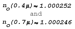
1,000 1.000274
950 1.000260
900 1.000246

(b) Temperature Dependence

Conditions: 5455 Å, 1013.3 mb

T, °C n

0 1.000292
15 1.000277
30 1.000263

(c) Wavelength Dependence

Conditions: 1013.3 mb, 15°C

Lambda, Å n

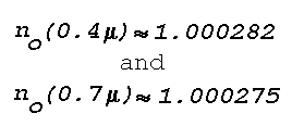
4,000 1.000282
5,000 1.000278
6,000 1.000276
7,000 1.000275
8,000 1.000275

[[1002]]


where k is a wavelength-dependent constant, P and T are the pressure and temperature, and R is the gas constant. The refractive index of a mixture of gases, such as the earth's atmosphere, is generally assumed to obey the additive rule, that is, the total value of n-1 is equal to the sum of the contributions from the constituent gases weighted by their partial pressures. When the atmosphere is considered as a mixture of dry air and water vapor,

Additive Rule expr 1

or

Additive Rule expr 2

where P denotes the total pressure of the mixture, e the partial water vapor pressure and the subscripts d and v refer to dry air and water vapor, respectively. Using Eq. (1), the refractive index n of the moist air at any temperature T and pressure P can be written

Refr Index vs T & P

where nd and nv are the refractive indices at Po and To. For Lambda = 5455Å (about the center of the visible spectrum), at Po = 1013.3 mb (760 mm Hg) and To = 273°K, nd = 1.000292 and nv = 1.000257, so that

Refr Index 5455 Angstr

For P = 1013.3 mb, maximum values of e/P (air saturated with water vapor) for a range of tropospheric temperatures are as follows:

T(°K) 273 283 288 293 298 303
e/P 0.006 0.012 0.017 0.023 0.031 0.042

It is evident that in problems related to terrestrial light refraction the effects of humidity on the atmospheric refractive index are negligible. It is of interest to compare the formula for the optical refractive index with that for radio waves in the centimeter range. The latter can be written

Refr Index, cm Radio Waves

[[1003]]


The formula for the optical refractive index can be written

Opt Refr Index

where Rd = gas constant for dry air. By introducing k as a function of wavelength (Johnson, 1954), a final expression for the optical refractive-index in the atmosphere can be written as

Opt Refr Index (final)

where the Sigmao2 are resonance lines and Sigma is the wavenumber in inverse microns (i.e. 1/Lambda). The latest equation is (Edlén, 1966):

Latest Eqn (Edlen)

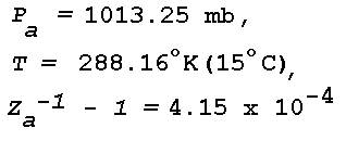
where na is the refractive index of dry air containing 0.03% CO2. Pa is the partial pressure of dry air, and Za-1 is the inverse compressibility factor for dry air (Owens, 1967). Za-1 is very close to unity; for

P, T, Z values

The standard value of Za-1 is assumed, i.e., the constant is

77.497 x 1.000415 ~ 77.53.

Table 1 gives the range of n for various ranges of atmospheric pressure, temperature, and wavelength. The listed values are of sufficient accuracy for a discussion of optical mirage. For a more recent version of Eq. (2) and differences in n smaller than 10-6 reference is made to the detailed work by Owens (1967).

Table 1 shows that the optical refractive index of the atmosphere is a relatively small quantity and that its largest variations with temperature, pressure and wavelength are of the order of 10-5. Such small changes in the refractive index correspond to relatively small changes in the direction of optical-energy propagation. Hence, an optical image that arises from atmospheric light refraction cannot be expected to have a large angular displacement from the light source.

[[1004]]


BACK To Section 3


C. Snell's Law of Refraction

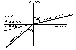
Snell's law, formulated for the refraction at a boundary, may be stated as follows: the refracted ray lies in the plane of incidence, and the ratio of the sine of the angle of incidence to the sine of the angle of refraction is constant. The constant is equal to the ratio of the indices of refraction of the two media separated by the boundary. Thus, Snell's law of refraction requires that:

Snell's Law

where phi and phi' are the angles of incidence and refraction respectively in the first and second medium, while n and n' are the corresponding values of the refractive index (see Fig. 1).

Snell's Law

Figure 1: Snell's Law

Click on Thumbnail to see Full-size image.

The angle of refraction (phi') is always larger than the angle of incidence (phi) when n > n', and the direction of energy propagation is from dense-to-rare. The critical angle of incidence (phic) beyond which no refracted light is possible can be found from Snell's law by substituting phi' = 90°. Thus,

Critical Angle

[[1005]]


For all angles of incidence > phic the incident energy is totally reflected, and the angle of reflection equals the angle of incidence (Goos and Haenchen, 1947).

Mirages arise under atmospheric conditions that involve "total reflection." Under such conditions the direction of energy propagation is from dense-to-rare, and the angle of incidence exceeds the critical angle such that the energy is not transmitted through the refracting layer but is "mirrored." The concept of total reflection is most rigorously applied by Wegener in his theoretical model of atmospheric refraction (Wegener, 1918).

Snell's law can be put into a form that enables the construction of a light ray in a horizontal layer wherein the refractive index changes continuously. Introducing a nondimensional rectangular phi ,z coordinate system with the x-axis in the horizontal,

Refrac Index Change

where Phi denotes the angle between the vertical axis and the direction of energy propagation in the plane of the coordinate system. Snell's law can now be applied by writing

Snells law applied (tan)

and

Snells Law applied (sin)

where no and phio are initial values. Substitution gives

Diff eq

When the refractive index n is expressed as a continuous function of x and z, the solution to the differential equation (3) gives a curve in the x,z plane that represents the light ray emanating to the point (no, phio). For example, when n2 decreases linearly with z according to

Z decreases linearly

[[1006]]


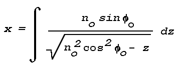
Eq. (3) can be integrated in the form

eq (3) Integrated

For an initial refractive index no and an initial direction of energy flow Thetaointegration between 0 and z gives:

eq (3) Integrated, 0 to Z

This equation represents a parabola. Hence, for a medium in which n changes with z in the above prescribed fashion, the rays emanating from a given light source are a family of parabolas.

When the ordinate of the nondimensional coordinate system is to represent height, z must represent a quantity az', where z' has units of height and a is the scale factor.

By introducing more complicated refractive-index profiles into Eq. (3), the paths of the refracted rays from an extended light source can be obtained and mirage images can be constructed. Tait and other investigators have successfully used this method to explain various mirage observations.

Application of Eq. (3) is restricted to light refraction in a plane- stratified atmosphere and to refractive-index profiles that permit its integration.

BACK To Section 3


D. Partial Reflections from Atmospheric Layers

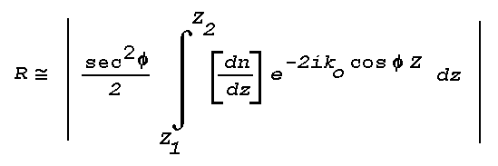
The theory of ray tracing or geometrical optics does not indicate the existence of partial reflections, which occur wherever there is an abrupt change in the direction of propagation of a wavefront. An approximate solution to the wave equation may be obtained for the reflection coefficient applicable to a thin atmospheric layer (Wait, 1962):

Partial Reflections

[[1007]]


where R is the power reflection coefficient, Phi the angle of incidence, Z is height through a layer bounded by Z1 and Z2, and Ko is the vacuum wavenumber

Vacuum Wave #

The equation is generally valid only when the value of R is quite small, say R < 10-4.

This result can be applied to atmospheric layers of known thickness and refractive index distribution; the most convenient model is that in which

Atmospheric Layer Model

everywhere else. Although some authors have argued that the reflection coefficient using this model depends critically upon the discontinuity in du/dz at the layer boundaries, it can be shown using continuous analytic models that the results will be the same for any functional dependence so long as the transition from dn/dz = 0 to dn/dz = const. occurs over a space that is not large compared to the effective wavelength. The effective wavelength is defined as Lambda·sec (Phi). For the simple linear model, R is given by

Reflection Coefficient

where

alpha

Delta·n is the total change in n through the layer, and h is the thickness of the layer,

Layer Thickness

For large values of h/Lambda, and hence large values of Alpha, the term sin (Alpha)/Alpha may be approximated as 1/Alpha for maxima of sin Alpha. Since h/Lambda is always large for optical wavelengths, e.g.

h/lambda ratio

for a layer 1 cm thick, the power reflection coefficient may be approximated by

Power Reflection Coefficient

Atmospheric layers with

Delta n

and h = 1 cm are known to exist in the surface boundary layer, e.g. producing inferior mirage. For visible light with a "center wavelength" of 5.6xl0-5 cm (0.56µ), Lambdao/h is thus 5.6x10⁻⁵. R then becomes

R (visible Light)

[[1008]]


This is a very small reflection coefficient, and light from even the brightest sources reflected at normal incidence by such a layer would be invisible to the human eye. The situation may be different at grazing incidence or large Phi; for a grazing angle of 1°, Phi = 89°,

Grazing Incidence

and

Grazing Incidence, Value of R

The critical grazing angle, Thetac, for a total reflection for the thin layer under discussion is given by

Grazing Incidence, Theta crit

which yields a value of 0.007746 rad or 26.6'. Substituting Phi = 89° 33.4' in the equation for R gives

Value of R

Since the human eye is capable of recording differences at least as great as 3.5x10⁻⁸ (Minnaert, 1954), partial reflections of strong light sources may occasionally be visible. The theoretical treatment discussed here shows that as the critical angle for a mirage is exceeded there should be a drop in reflected intensity on the order of 10-7 - 10-8, so that instead of a smooth transition from totally to partially reflecting regimes, there should be a sharp decrease giving the impression of a complete disappearance of the reflection. This is in agreement with observation. The theory also indicates that faint images produced by partial reflection of very bright light sources, e.g. arc lights, may be seen at angles somewhat larger than the critical angle for a true mirage.

BACK To Section 3


E. Spatial Variations in the Atmospheric Index-of-Refraction

As dictated by Snell's law, refraction of light in the earth's atmosphere arises from spatial variations in the optical refractive index. Since

n as func of P, T, Lambda

according to Eq. (2), the spatial variations of n(Lambda) can be expressed in terms of the spatial variations of atmospheric pressure and temperature. Routine measurements of the latter two quantities are made by a network of meteorological surface observations and upper-air soundings. When the optical wavelength dependence of n is neglected, Eq. (2) takes the form

Eq 2 Modified

[[1009]]


and the gradient of n is given by

Gradient of n

Optical mirages are most likely to form when atmospheric conditions of relative calm (no heavy cloudiness, no precipitation or strong winds) and extended horizontal visibility (<10 miles) are combined with large radiative heating or cooling of the earth's surface. Under these conditions the vertical gradients of pressure and temperature are much larger than the horizontal gradients, i.e., the atmosphere tends to be horizontally stratified.* Thus,

Stratification 1

or

Stratification 2

Stratification 3

Thus, the spatial variation in the refractive index, i.e., light refraction, depends primarily on the vertical temperature gradient. When ðn/ðz is negative and the direction of energy propagation is from dense to rare, the curvature of light rays in the earth's atmosphere is in the same sense as that of the earth's surface. Equation (4) shows that ðn/ðz is negative for all vertical gradients of temperature except those for which the temperature decreases with height > 3.4°C/l00 m. No light refraction takes place when ðn/ðz  = 0; in this case ðn/ðz  = -3.4°C/100 m. which is the autoconvective lapse rate, i.e., the vertical temperature gradient in an atmosphere of constant density. Table 2 gives the curvature of a light ray in seconds of arc per kilometer for various values of ðn/ðz near the surface of the earth (standard P and T). When ray curvature is positive, it is in the same sense as an earth's curvature.
*When horizontal gradients in the refractive index are present, the complex mirage images that occur are often referred to as Fata Morgana. It is believed, however, that the vertical gradient is the determining factor in the formation of most images.

[[1010]]


Table 2

CURVATURE OF LIGHT RAYS FOR VARIOUS VALUES OF VERTICAL
TEMPERATURE GRADIENT AT STANDARD CONDITIONS OF PRESSURE

(1013.3 mb) AND TEMPERATURE (273°K)


Partial Deriv T/z
(°C/100m)
CURVATURE OF LIGHT RAYS ("/km)

-3.4 0
-1.0 5.3
-0.5 6.4
0 7.5
+6.9 22.7
+11.6 33.0

From Table 2 it is evident that two types of vertical temperature variation contribute most to the formation of mirages; these are temperature inversions [( ðT/ðZ )>0] and temperature lapse rates exceeding 3.4°C/100m (the autoconvective lapse rate). Superautoconvective lapse rates cause light rays to have negative curvature (concave upward), and are responsible for the formation of inferior mirages (e.g., road mirage). The curvature of the earth's surface is 33"/km, and thus whenever there is a sufficiently strong temperature inversion, light rays propagating at low angles will follow the curvature of the earth beyond the normal horizon. This is the mechanism responsible for the formation of prominent superior mirages.

BACK To Section 3


F. Meteorological Conditions Conducive to the Formation of Mirages

The strength and frequency of vertical temperature gradients in the earth's atmosphere are constantly monitored by meteorologists. The largest temperature changes with height are found in the first 1,000 m above the earth's surface. In this layer, maximum temperature gradients usually arise from the combined effects of differential air motion and radiative heating or cooling.

The temperature increase through a low-level inversion layer can vary from a few degrees to as much as 30°C during nighttime cooling of the ground layer. During daytime heating, the temperature can drop by as much as 20°C in the first couple of meters above the ground

[[1011]]


(Handbook of Geophysics and Space Environments, 1965). Large temperature lapses are generally restricted to narrow layers above those ground surfaces that rapidly absorb but poorly conduct solar radiation. Temperature inversions that are due to radiative cooling are not as selective as to the nature of the lower boundary and are therefore more common and more extensive than large lapses. Temperature inversions can extend over horizontal distances of more than 100 km. Large temperature lapses, however, do not usually extend uninterrupted over distances more than a couple of kilometers.

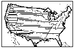
At any given location, the frequency of occurrence of large temperature lapses is directly related to the frequency of occurrence of warm sunny days. Fig.2 shows the average distribution of normal summer sunshine across the United States (Visher, 1954). More than seventy percent of the possible total is recorded in a large area extending from the Mississippi to the West Coast. Consequently, low-level mirages associated with large temperature lapses may be rather normal phenomena in this area. Distribution for summer and winter of the frequency of occurrence of temperature inversions <150 m above ground level are shown for the United States in Fig. 3 (Hosler, 1961). The data are based on a two-year sampling period. Figure 4 shows the distribution across the United States of the percentage of time that the visibility exceeds 10 km (Eldridge, 1966). When Figs. 3 and 4 are combined it is seen that large areas between roughly the Mississippi and the West Coast have a high frequency of extended horizontal visibility and a relatively high frequency of low-level temperature inversions. These meteorological conditions are favorable for the formation of mirages. On the basis of the climatic data shown in Figs. 2, 3, and 4 it can be concluded that at some places a low-level mirage may be a rather normal phenomenon while in other places it may be highly abnormal. An example of the sometimes daily recurrence of superior mirage over the northern part of the Gulf of California is discussed by Ronald Ives (1968). Temperature inversions in the cloud-free atmosphere are often recorded at heights up to 6,000 m above the ground. These elevated inversions usually arise from descending air motions, although radiative processes can be involved when very thin cirrus clouds or haze layers are present. Narrow

[[1012]]


Normal Sunshine

Figure 2: Normal Summer Sunshine

Click on Thumbnail to see Full-size image.

Inversion Freq

Figure 3: Inversion Frequency

Click on Thumbnail to see Full-size image.

Visibility Distr

Figure 4: Visibility Distribution

Click on Thumbnail to see Full-size image.

[[1013]]


layers of high-level temperature inversion, e.g., 4°C measured in a vertical distance of a few meters, extending without appreciable changes in height for several tens of kilometers in the horizontal direction have been encountered (Lane, 1965). Such inversions are conducive to mirage formation when they are accompanied by extended visibility in the horizontal as well as in the vertical. A climatology of such inversions can be obtained from existing meteorological data.

BACK To Section 3


BACK To Top


4. Visual Characteristics of Light-Refraction Phenomena
in the Cloud-Free Atmosphere


A. General
B. Characteristics of the Mirage
C. Light Scattering by Aerosol Particles

A. General

Light refraction as it occurs in the earth's atmosphere can be divided into random refraction and systematic or regular refraction (Meyer-Arendt,1965). Random refraction is due to the small-scale (meters or less), rapid (seconds) temperature fluctuations associated with atmospheric turbulence, and is responsible for such phenomena as the scintillation of stars and planets, and the shimmer of distant objects. Systematic or regular refraction is the systematic deviation of a propagating wavefront by temperature gradients that are extensive in space (on the order of several kilometers or more) and persistent in time (on the order of an hour or more). Systematic refraction leads to the apparent displacement of a light source from its true position. The light source can be outside the atmosphere (astronomical refraction) or within the atmosphere (terrestrial refraction). Random and systematic refraction generally act simultaneously so that the associated effects are superposed.

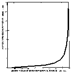
Values of astronomical and terrestrial refraction computed for average atmospheric temperature structure are well documented. The angular difference between the apparent zenith distance of a celestial body and its true zenith distance (as observed from a position near sea level) is zero at the zenith but gradually increases in magnitude away from the zenith to a maximum of about 35 mm. of arc on the horizon. Thirty-five minutes of arc is very nearly equal to the angle subtended by the sun's or moon's disc (30 mm.), so that when these heavenly bodies appear just above the horizon they are geometrically just below it. Figure 5 shows average values of astronomical refraction as a function of zenith angle. The very large

[[1014]]


Astro. Refraction

Figure 5: Astronomical refraction

Click on Thumbnail to see Full-size image.

[[1015]]


increase in refraction toward the horizon causes frequently observed distortions of the sun's or moon's disc. Normally, the differential refraction between the point of the lower limb (touching the horizon) and the point of the upper limb (30 min. above the horizon) amounts to about 6 min., so that when on the horizon, the sun or moon appears to an earth-bound observer as an ellipse rather than a circle. Recent observations indicate that the setting sun or moon as seen from outside the earth's atmosphere also appears flattened due to refraction (Cameron, et al., 1963). Under abnormal atmospheric temperature conditions, the differential refraction can be so large that the rising or setting sun or moon appears in grossly distorted form(O'Connell 1958).

Terrestrial-refraction angles have been computed as a function of zenith angle and altitude of the luminous source (Link and Sekera 1940; Saunders, 1963). Depending on height, refraction angles computed with reference to sea level vary from <5 sec. of arc at a zenith angle of 5° to <12 min. of arc at a zenith angle of 86°. Above 42 km refraction is negligible.

The importance of the seemingly small astronomical and terrestrial refraction on visual observations can be evaluated as follows. Resolving theory and practice have established that the human eye (which is a lens system) cannot resolve, separate clearly, or recognizably identify two points that subtend an angle to the eye of less than 1/16° = 3.75 min. (Tolansky 1964; Minnaert, 1954). Under standard atmospheric-temperature conditions, angular deviations due to astronomical and terrestrial refraction that are larger than 3.75 min. occur when distant light sources are less than about 14° above the horizon (zenith angle larger than about 76°. Hence, the effects of systematic atmospheric refraction on visual observations of a distant light source (point source) which is less than about 76° from the zenith can be considered negligible because the average human eye cannot clearly separate the source from its refracted image. However, when the luminous point source is located at about 14° or less from the horizon, the location and appearance of the source as seen by a distant observer are those of its refracted image. Close to the horizon, refraction becomes large enough to affect the visual observations of

[[1016]]


extended sources. Thus, it is evident that the evaluation of observations of light sources that are close to the horizon requires knowledge of the characteristics of refracted images.

BACK To Section 4


B. Characteristics of the Mirage


1. Geometry of Illumination and Viewing
2. Number and Shape of Mirage Images
3. Effects from Focussing and Interference
4. Refractive Separation of the Color Components of White Light (Color Separation)
5. Effects from Atmospheric Scintillation

1. Geometry of Illumination and Viewing

When a luminous source is near the horizon, (i.e., near the horizontal plane of view of its observer) the optical path length through the atmosphere is maximum. In this case, systematic refraction is at a maximum and the visual effects can be large when layers of anomalous vertical temperature gradient are present. There are, however, important practical limitations as to how much the apparent position of a refracted image can differ from the true position of the source. Limits in the viewing geometry can be determined by Snell's law using limiting values of the optical refractive index.

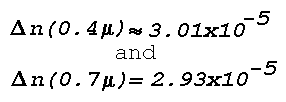
Observations indicate that a temperature change of 30°C across relatively thin (<1 km) layers of temperature inversion or temperature lapse approximates the maximum change that can be expected (Ramdas, 1951). Thirty degrees Centigrade correspond to a refractive-index change of about 3x10⁻⁵ (Brunt, 1929). Combining this maximum change in the optical refractive index with the range of values listed in Table 1, the following limits are suggested as the range of the refractive index (n) that can be expected in the lower cloud-free atmosphere.

Range of n

Substitution of the upper and lower limit into the equation for total reflection gives

Sin Phi crit

and

Phi crit

Hence, when a horizontal layer or boundary across which n has the assumed maximum variation of 1.00029 to 1.00026 is illuminated by a light source (direction of propagation from dense to rare), the angle of incidence has to exceed 89.5° (½° grazing angle) in order to get total reflection and a possible mirage image. For all practical purposes, 0.5° can be considered as the near-maximum angle of illumination that will allow for formation of a mirage. When the refractive index decreases with height

[[1017]]


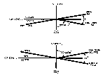
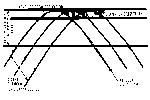
across the boundary and illumination is from below, the mirage image appears at a maximum angular distance of about 1° above the true position of the light source as illustrated in Fig. 6a . Hence, one degree of arc must represent about the maximum angular distance that can be expected between the true position of the light source and its refracted image. When the image appears above the true position of the source, the mirage is referred to as a superior mirage. When the refractive index increases with height and illumination is from above, an inferior mirage appears, i.e., the image lies below the true position of the source as shown in Fig. 6b. In terms of vertical temperature gradient, the superior mirage is associated with an inversion and the inferior mirage with a large temperature-lapse.

It is evident that the presence of a layer of large temperature gradient is necessary but not sufficient for mirage formation. A remaining requirement is the presence of light that illuminates the layer at grazing incidence. The incident light can originate from a physical source such as sun, moon, or planet, or it can be skylight or sunlight reflected from the ground.

Whether the mirage is observed or not depends on the position of the observer with respect to the light source and the refracting layer. The planar geometry involved in a mirage observation can be illustrated by applying Eq. (3):

Eq 3 Applied

to a rectangular coordinate system in which the abscissa coincides with the ground. For simplicity it is assumed that

Ref Index vs Height

(i.e., the refractive index, n , decreases with height), so that the solution to Eq. (3) represents a family of parabolas of the form

Parabola Family Form

(In applying Eq. (3), z represents az' where z' has units of height and a is the scale factor). The family of parabolas, sketched in Fig. 7, can be thought of as representing the light rays from a point source located at the origin of the coordinate system. Using the upper and lower limit

[[1018]]


Fig 6

Figure 6: Mirage Geometry

Click on Thumbnail to see Full-size image.

[[1019]]


of the optical refractive index, no = 1.00029 and n = 1.00026, the largest horizontal distance (D) is covered by the light ray for which Thetao = 89.5° (angles are exaggerated in Fig. 7). All mirage images must be observed within this distance (see Fig. 7). D can be expressed in terms of the height (H) of the refracting layer as follows. For each member of the family of parabolas, z is maximum at the point where (dz/dx) = 0, i.e., at the point

z Maximum

Since each member is symmetric with respect to this point also,

Ratio D/H

Hence, D ~ 500H, i.e., all mirage images in this particular case are observed within a distance from the light source that is about 500 times the thickness of the refracting layer. For example, when the thickness of the refracting layer is 10 meters, no mirage observations of a particular object are likely beyond a distance of 5 km. At about 5 km an image of the object may appear at an elevation of about 0.5°, while within 5 km images may appear at increasingly lower elevation angles until the eye can no longer clearly separate the image from the source.

The preceding discussion applies only to the case where the observer is located within, or at the boundary of, the mirage-producing layer, If the observer is some distance above or below the mirage-producing layer, mirages of much more distant objects may appear.

From the above, it is evident that principal characteristics of the optical mirage are the small elevation angles under which the phenomenon is observed (<1°) and the large distances (tens of kilometers) between observer and "mirrored" object that are possible. The geometry of the mirage explains why many observations are made on or near horizontally extensive, flat terrain such as deserts, lakes, and oceans and frequently involve images viewed through binoculars (oases, ships, islands, coastal geography). Furthermore, the above geometry illustrates that the duration of a mirage observation is critically dependent on whether or not the source and observer are in relative motion. For example, when the light source is moving in such a way that the angle of illumination, Thetao, oscillates around the critical angle, a stationary observer located at A in Fig. 7 may see a mirage image that alternately appears and disappears.

[[1020]]


Fig 7

Figure 7: Light Ray Parabolas

Click on thumbnail to see full-size image.

[[1021]]


On the other hand, when the observer is moving relative to the source (from A to B in Fig. 7), the mirage image can change elevation, thereby creating an illusion of motion.

BACK To Section 4B


2. Number and Shape of Mirage Images

It has been recognized that systematic refraction of the light from a single source can lead to multiple mirage images the shapes of which can be complicated. The early observations by Vince (1798) and Scoresby (1820) included sightings of completely or partially inverted images of a single distant ship. From a coastal position on the English Channel, John Parnell (1869) observed five elevated images, all in a vertical line, of a lighthouse on the French Coast. All five images had different shapes. During their observations in Spain, Biot and Arago (1809) observed up to four elevated images of a distant (161 km) light signal. The images disappeared and reappeared intermittently and at times joined to form a narrow vertical column of light which subsequently separated into two parts, the lower part appearing red and the upper part appearing green. The above observations resulted from abnormal atmospheric light-refraction the observed images were distant, and in most cases detailed descriptions were made with the aid of binoculars.

Practically all theoretical and experimental investigations of optical mirages (e.g., Wollaston 1800; Hillers 1914; R. W. Wood 1911) have been concerned with demonstrating the number and shape of observed images. Tait's theoretical treatise and Wollaston's laboratory experiment can be considered classical examples. Tait's terrestrial-refraction model represents a horizontally stratified atmosphere, and a vertically finite refracting layer with a continuous change in refractive index. Under these assumptions the paths of light rays are represented by the solution to the differential equation:

Ray Paths

where n can be expressed as a continuous function of height (z). Tait shows that the number and shape of mirage images depend on the detailed structure of the refractive-index profile (temperature profile) within the refracting layer. For example, the elevated mirage image of a distant

[[1022]]


object becomes inverted when the refractive index in the upper part of the refracting layer decreases more rapidly with height than in the lower part. This "classical" explanation of image inversion is illustrated in Fig. 8. Shown are the paths of two light rays obtained from solving Eq. (3) for n2 = no2 - z2. Thus, the refractive-index gradient ( ðn/ðz ) in the upper part of the refracting layer is much larger than in the lower part. When the observer's eye is placed at the origin of the X,z coordinate system, observed image-inversion arises from the crossing of light rays.

Apparent vertical stretching (elongation, towering) of a luminous object due to refraction is illustrated in Fig. 9. For the sake of clarity, height and elevation angles are exaggerated. A horizontal refracting layer is assumed that is 10 meters thick and through which the refractive index (n) decreases with height (z) from 1.00029 to 1.00026 according to the relation n2 = (1.00029)2 - z2. Hence, the refraction of a light ray increases with height. It can be shown that a 10-m-high luminous object placed at a horizontal distance of 2 km subtends an angle of approximately 26.5' at the origin. In the absence of the refracting layer the object would have subtended an angle of 16.8'. The apparent vertical stretching is brought about by the refractive-index profile; i.e., the increase in "bending' of the light rays with height elevates the upper part of the luminous source. Vertical stretching can lead an observer to underestimate the true distance to the luminous object. Vertical shrinking (stooping) of an extended object can be demonstrated similarly by assuming a refractive-index profile that is associated with a decrease of the gradient with height. In the case of vertical shrinking, the true geometric distance to the object involved is usually smaller than the apparent distance.

Many examples of image inversion, vertical stretching, and shrinking due to abnormal atmospheric refraction are given in The Marine Observer.

Tait's theoretical approach, the emphasis on the refractive-index profile, is basic to many other theoretical investigations of the mirage. For example, Wilhelm Hillers (1913) shows how two refracted images of a single light source can be formed when the profile in the refracting layer is such that the refracted rays are circular. Fig. 10 shows the

[[1023]]


Fig. 8

Figure 8: Image Inversion

Click on Thumbnail to see Full-size image.

Fig 9

Figure 9: Image Elongation

Click on Thumbnail to see Full-size image.

[[1024]]


North Atlantic Ocean

S.S. Bristol City. Captain A. L. Webb, O.B.E. Sydney (C.B.) to Swansea. Observers, the Master and Mr. R. Whitman, 3rd Officer.

18th September, 1952, 2000 G.M.T. A vessel approaching end-on at 15 miles, with hull just visible, appeared to have elongated masts and funnel (Fig. 1). At

Mar Obs 123

Ship Images

Click on Thumbnail to see Full-size image.

10 miles the hull also became enlarged and the bow wave, very prominent (Fig. 2), appeared to move up and down the length of the stem. At 5 miles the vessel resumed normal shape. At the same time and position a second vessel, when 10 miles to the s'ward, suddenly developed an inverted image which lasted for 15 min. before disappearing (Fig 3.). A few minutes later the wake appeared, very prominent, resembling heavy surf which lasted another 10 min. (Fig. 4). Before passing

Mar Obs 45

Ship Images

Click on Thumbnail to see Full-size image.

out of view the vessel appeared to take on a "block" shape (Fig. 5), only resuming its normal shape at brief intervals as the vessel dipped in the slight swell. Sea Temp. 53°F, air Temp. 52°, wet bulb 50°. Calm sea, slight swell.

Position of ship: 48°32'N, 44°50'W.

Note. This observation is also one of superior mirage and in Fig. 3 the inverted image is clearly seen. In Figs. 1 and 2 the vertical extension and distortion known as looming is well marked.

(Reproduced from The Marine Observer, Vol. 23, No. 161, p. 143, July 1953)

[[1025]]


South Atlantic Ocean

S.S. Tenagodus. Captain W. Broughton. Cape Town to Algiers. Observers, Mr. J. J. Diston, Chief Officer, and Mr. J. F. Gristwood, 2nd Officer.

Tanker

Tanker Image

Click on Thumbnail to see Full-size image.

2nd March, 1955, 1730-1800 L.T. About one hour after leaving Cape Town abnormal refraction was noticed around the horizon from SW. through N. to E. A large tanker, 8 miles distant on the port beam, was considerably distorted; the funnel was greatly elongated and appeared taller then the masts, and swayed occasionally. The radar scanner appeared suspended well above the ship. On the starboard bow, 28 miles distant, a hill 280 ft high at Ysterfontein Point was observed to have an inverted image; these gradually telescoped until the hill appeared as a block.

Temperatures: air 66°F, sea 59°. Slight sea, low swell.

Position of ship: 33°49'S., 18°16'E.

Inverted Images

Inverted Images

Click on Thumbnail to see Full-size image.

(Reproduced from The Marine Observer, Vol 26, No. 172, April 1956)

[[1026]]


Fig. 10

Figure 10: Double-Image Refraction

Click on Thumbnail to see Full-size image.

[[1027]]


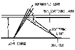
geometry of this special case. The refracting layer lies above the observer and the distant light source. Refraction below the refracting layer is assumed negligible, i.e., light rays are rectilinear. When the light rays penetrating the refracting layer are circles concentric about M, two separate rays emanating from the light source reach the observer's eye and all rays intermediate and outside these two fail to be tangent to a concentric circle. Consequently, the observer views two separate images. An example of three observed images of a distant hill is shown in the figure on page 1026 in an excerpt from The Marine Observer.

Tait's approach cannot be applied indiscriminately to all mirage phenomena because integration of Eq. (3) is restricted to a selected range of refractive index profiles. Furthermore, the effect of the earth's curvature is excluded so that only mirage phenomena associated with not-too-distant objects can be considered. Hence, Tait's model cannot explain mirage observations associated with extraterrestrial sources such as the sun or the moon.

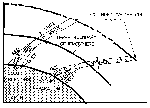
Alfred Wegener (1918) has developed an atmospheric refraction model that explains distorted images of the sun, moon, planets, or stars that are often observed near the horizon. Wegener assumes a spherically stratified atmosphere and reduces the refracting layer to a refracting boundary or surface of total reflection. Wegener demonstrated that when the refracting boundary lies above the observer and the sun is on the horizon, the boundary refracts the solar light rays in such a way that the observer views two separate images of the solar disc, a flattened upper image and a distorted lower image. Fig. 11 shows the successive form of the two images for a setting sun or moon in the presence of a 7° temperature-inversion layer 50 m above the observer* as computed by Wegener. The degree of deflection of the incoming light rays and consequently the degree of distortion of the solar disc depends on the refractive-index change or temperature change across the reflecting boundary. When the temperature change is small, only a single distorted image of the solar disc appears. When the change across the boundary is

[[1028]]


Fig. 11

Figure 11: Sunset/Moonset Mirages

Click on Thumbnail to see Full-size image.

[[1029]]


very large only the the flat upper part of the "split" solar image is seen, so that the setting sun appears to vanish above the horizon. When the atmosphere is highly stratified, i.e., when several horizontal refracting boundaries are present, the setting sun can appear like a Chinese Pagoda or like a stack of discs. The refracted images of the setting sun computed by Wegener's model agree closely with those photographed and described by D. J. K. O'Connell (1958) in connection with a study of the green and red flash phenomena.

Wegener's model is not restricted to luminous sources outside the earth's atmosphere. It can be applied to distant terrestrial objects such as mountains from which emitted light rays are at grazing incidence to the top of the refracting boundary. Wegener's model of atmospheric refraction illustrates the characteristics that are basic to many spectacular risings or settings of sun, moon, or planet. Following are three accounts of such abnormal atmospheric-refraction phenomena as given in The Marine Observer.

The atmospheric-refraction models of Tait and Wegener quantitatively explain the basic characteristics of the most commonly observed mirage-images. Other theoretical investigations are available that discuss various special aspects. For example, the theory of the superior mirage by Odd Haug explains the appearance of up to four images from a single source. Wilhelm Hillers treats the special case of a lateral mirage, i.e., the refraction of light when the refractive-index gradient is horizontal, as may be the case along a wall heated by solar radiation. Koji Ilidaka and Gustav Forster discuss the theory of refraction when the surfaces of constant density in the atmosphere are somewhere between horizontal and vertical. Together, these theoretical models explain adequately the varying ways in which a mirage image can appear to an observer. Currently, there is no single model with a numerical solution to all aspects of the mirage.

[[1030]]


ABNORMAL REFRACTION

Off Coast of Portugal

M/V. Australind. Captain J. F. Wood. Port Said to Bremen. Observer, Mr. D. Ewan, Chief Officer.

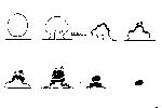
27th April, 1950, 1546-1549 G.M.T. The accompanying sketches picture the sequence of shapes assumed by the sun as a result of refraction.

Rising Sun

Rising Sun

Click on Thumbnail to see Full-size image.

After Clearing the horizon the sun slowly regained its normal proportions and at an altitude of 1½° no refraction was apparent. No land was visible near the phenomenon. Wind N, force 4. Barometer 1020.3 mb, air temp. 58°F. Sky cloudless.

Position of ship: Latitude 38° 04'N., Longitude 9° 24'W.

(Reproduced from The Marine Observer, Vol. 21, No. 152, p. 80, April 1951)

[[1031]]


ABNORMAL REFRACTION

North Atlantic Ocean

O.W.S. Weather Recorder. Captain A. W. Ford, At Ocean Weather Station A. Observer, Mr. J. Ballantyne, 3rd Officer.

5th May, 1955, 2220-2240 G.M.T. Towards sunset abnormal refraction was observed, and for a while two suns were visible. A false sun was seen for half its

Double Sun

Double Sun

Click on Thumbnail to see Full-size image.

diameter on the horizon, and touching the real sun above. The real sun was partly obscured by cloud. The false sun persisted for 3 or 4 min after the real sun had set. A vertical ray with reddish coloration extended to about 4° above the real sun.

(Reproduced from The Marine Observer, Vol. 26, No. 172, April 1956)


ABNORMAL REFRACTION

English Channel

M.V. Timaru Star. Captain H. W. McNeil. London to Curacao. Observer, Mr. N. Johnson, 3rd Officer.

Double Sun

Double Sun

Click on Thumbnail to see Full-size image.

4th January, 1956. While proceeding down the English Channel at 0800 G.M.T., shortly after sunrise, the sun was observed to have a distorted appearance (sketch 1). By 0810 while the sun continued to rise a false "sun" began to set. Two minutes later there was a distinct gap between the true sun and the false and by 0814 the false sun was no longer visible. In the area of the rising true sun the sky was clear and a bright orange in color. A phenomenon similar to sketch 2 was observed at sunset on the same day.

Position of ship: 50° 05'N., 02° 04'W.

(Reproduced from The Marine Observer, Vol. 27, No. 175, p. 13, 1957)

[[1032]]


BACK To Section 4B


3. Effects from Focussing and Interference

A recent theoretical and experimental investigation of the optical mirage is presented by Sir C. V. Raman (1959). Sir C. V. Raman demonstrates that multiple, inverted images of a single object can arise from interference and focussing of the incident and reflected wavefronts near the boundary of total reflection. Raman's work, which is entirely based on wave theory, suggests the interaction of wavefronts within a refracting layer as a mechanism in mirage formation.

The occurrence of focussing and interference in situations that give rise to mirage, examined specifically by Raman, is also evident from various investigations based on geometrical optics. For example, the crossing of light rays mentioned in connection with image inversion implies interference of wavefronts at the points of intersection.

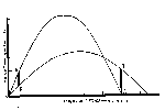
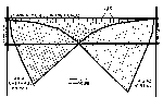
The visual effects from focussing and interference must be considered in particular when plane-parallel radiation (radiation from a very distant source) is incident on a layer of total reflection. In this case, there is a constant crossing of light rays within a relatively narrow region of the refracting layer, as illustrated in Fig. 12 (for the sake of clarity, height and elevation angles are exaggerated). In Fig. 12, a circular collimated light-beam of diameter A is incident on the lower boundary of a temperature-inversion layer at angle equal to or exceeding the critical angle for total reflection. Interference of the incident and reflected wavefronts occurs in a selected layer near the level of total reflection. This layer, shaded in Fig. 12, has a maximum thickness B, which is dependent on A. In the absence of absorption, the amount of radiant energy, flowing per unit time through Pi·A2 equals that flowing through Pi·B2. When B is less than A, the energy density at B is larger than at A, so that the brightness of the refracted light beam increases in the layer of interference.

An example of the ratio of A to B can be Given with the aid of Eq. (3). It is assumed that the optical refractive index through the inversion layer varies from no = 1.00029 to n = 1.00026 according to n2 = no2 - z. When the angle of incidence is near the critical angle for total reflection (Thetao ~ 89.5°), the light rays within the inversion layer are parabolas and

[[1033]]


Fig. 12

Figure 12: Energy in Inversion

Click on Thumbnail to see Full-size image.

[[1034]]


the level of total reflection coincides with the upper boundary of the inversion layer. Under these conditions, it can be shown that B/A = A/16H where H is the thickness of the temperature-inversion layer. When the diameter A of the incident light beam is less than 16H, B is less than A and a brightening or focussing occurs near the top of the inversion. When the angle of incidence of the light beam is larger than the critical angle, ~89.5°, the level of total reflection lies below the upper boundary of the inversion layer. In this case, brightening can still occur near the level of total reflection, but the restrictions on the required beam-diameter become rather severe. The above example, based on a special case, demonstrates that sudden brightening can be encountered near the upper boundary of a refracting layer when optical mirages are associated with a refracting layer that is thick with respect to the diameter of the incident light beam from a distant source and when the angle of incidence is near the critical angle.

Observations of the brightening phenomenon must be considered rare in view of the selective location of its occurrence within the temperature-inversion layer and the requirement of plane-parallel incident radiation. Upper-level inversions seem most likely to produce the phenomenon. Some photographs showing apparent brightening of "spike" reflections on the edge of the setting sun are shown in O'Connell (1958, c.f., p. 158).

Microscopic effects due to interference of wavefronts within the area of brightening are illustrated in Fig. 13. Wavefronts are indicated rather than light rays. Unless absorption is extremely large, light rays are normal to the wavefront. A train of plane-parallel waves is assumed incident on the lower boundary of a refracting layer in which the refractive-index decreases with height. When the angle of incidence equals the critical angle, the incident waves are refracted upon entering the refracting layer and are totally reflected at the upper boundary. The crests and troughs of the waves are indicated by solid lines and dashed lines, respectively. At the upper boundary, the wavefronts of the incident and reflected waves converge to a focus. The focus is called a cusp. The upper boundary of the refracting layer resembles a caustic,

[[1035]]


Fig. 13

Figure 13: Wavefront Diagram

Click on Thumbnail to see Full-size image.

[[1036]]


i.e., an envelope of the moving cusps of the propagating wavefronts. Because of the focussing of wavefronts, a large concentration of radiant energy is usually found along the caustic (see Raman, 1959). In the area where the incoming and outgoing wavefronts interact, destructive interference is found along AA' and CC' (troughs meeting crests), while constructive interference is found along BB' (incident and reflected waves have similar phase). Hence, brightness variations can be expected in the interference layer, as demonstrated by Sir C. V. Raman (1959). To what extent the microscopic effects from interference and focussing can be observed under actual atmospheric conditions of mirage is not known. Undoubtedly, the proper relation between refracting layer and distant light source must be combined with an observer's position near the upper boundary of the refracting layer. If the dark and bright bands in the area of interference can be observed, the observer could easily get the impression that he is viewing a rapidly oscillating light or a light that is drawing near and moving away at rapid intervals. Nighttime observations by airplane are most likely to provide proper evidence of this effect.

Currently, the focussing and interference effects are the least explored and consequently the least discussed of the various aspects associated with optical mirage.

BACK To Section 4B


4. Refractive Separation of the Color Components of White Light (Color Separation)

Due to the wavelength dependence of the optical refractive index, systematic refraction of white light leads to a separation of the composing colors. Visible effects of color separation are most frequently associated with astronomical refraction. In this case, the light enters the atmosphere at an upper boundary where n approaches unity for all wavelengths. At an observation site near sea level n is wavelength-dependent, so that from the upper boundary of the atmosphere to the observation site the individual color components are refracted at different angles. The basic composing color of white light may be assumed to be red (24%), green (38%), and blue-violet 38%); the red is refracted less than the green, while the green is refracted less than the blue-violet. The visual effects of color separation depend on the zenith

[[1037]]


angle of the extraterrestrial light source. When a white light source is more than 50° above the horizon, the color separation is simply too small to be resolved by the eye. Close to the horizon it can be observed only in the case of very small light sources. The principle of color separation in astronomical refraction is illustrated in Fig. 14. The light from an extended source enters the top of the atmosphere and is separated with respect to color in the order red, green, blue, and violet. A bundle of light rays of diameter D can be selected for which all colors, upon refraction, converge at O. Hence, an observer at O sees the entire color mixture as white. When the extended source has a diameter larger than D, an area rather than a single point of color blending is formed. However, when the diameter of the source becomes less than D, the point of color convergence, O, recedes from the location of the observer. Now the observer begins to see a gradual refractive separating of color such that red tends to lie below green, and green tends to lie below blue-violet (see Fig. 14).

The diameter of the light beam from a given extraterrestrial source decreases with respect to an earth-bound observer, with increasing distance from the zenith, as illustrated in Fig. 14. Thus, when the zenith angle increases, the apparent diameter D of the light source decreases rapidly to a minimum value on the horizon. Hence, the chance of having a light source of diameter less than D is greatest on the horizon. Therefore, color separation is observed most frequently on the horizon, when the light source is reduced to a bright point like a star or a minute portion of the solar or lunar disc. A prominent example of the visible effects of color separation is the so-called Green Flash. This phenomenon is sometimes observed when the sun disappears in a clear sky below a distant horizon. The last star-like point can then be seen to change rapidly from pale yellow or orange, to green, and finally, blue, or at least a bluish-green. The vividness of the green, when the sky is exceptionally clear, together with its almost instant appearance and extremely short duration, has given rise to the name "green flash" for this phenomenon.

[[1038]]


Fig 14

Figure 14: Refractive Color Separation

Click on Thumbnail to see Full-size image.

[[1039]]


The same gamut of colors, only in reverse order, occasionally is seen at sunrise. The observations of the Green Flash require an unusually clear atmosphere such that the sun is yellowish, and not red, as it begins to sink below the horizon. A red setting sun means that the blue and green portions of the spectrum are relatively strongly attenuated by the atmosphere and hence indicates that conditions are not favorable for seeing the greenish segment. Thus, the meteorological conditions required for observing color separation are even more stringent than those required for observing optical mirages. Examples of color separation associated with astronomical refraction are given on the following page in excerpts from The Marine Observer.

In terrestrial refraction the composing colors of white light are very seldom separated to the extent that the effects can be observed with the naked eye. When the wavelength dependence of the refractive index is put back into Eq. (4),

Wavelength Dependencs into Eq 4

Hence, for a given temperature inversion, the refractive index (n) decreases somewhat faster with height (z) for Lambda = 0.4µ (blue) than for Lambda = 0.7µ (red), so that the blue rays are refracted more than the red rays. However, the difference is generally too small to be resolved by the eye. Only under very special conditions can a visible effect be imagined. For example, when a 100-m-thick inversion layer is assumed to be associated with a Delta·T = 30°C, the change of the refractive index for blue light and red light is respectively,

Red/blue refractive index

When the optical refractive indices at the lower boundary of the inversion are

Refr indices, Inversion Lower Boundary

(corresponding to P =1013.3 mb and T = 15°C), values at the upper boundary are

Refr indices, Inversion Upper Boundary

When white light is incident at the lower boundary of the inversion at an angle Phio such that

Blue rays, total reflection

then the blue rays are totally reflected by the inversion layer but the red rays are transmitted. Hence, for Phio ~ 89° 33' 30" the blue rays are totally reflected, and for Phio ~ 89° 33' 54" the red rays are totally reflected. The visible effects of color separation that can arise when Phio fluctuates from

[[1040]]


SETTING OF THE PLANET VENUS

Indian Ocean

S.S. Strathnaver. Captain I. M. Sinclair. Australia to London. Observer, Mr. J. C. Vint, Supernumerary 2nd Officer.

6th December, 1957 at 2105 S.M.T. The accompanying sketch illustrates the

Venus

Setting Venus

Click on Thumbnail to see Full-size image.

changes observed in the planet as it was setting. Prismatic binoculars were used to observe the phenomena. Position of ship: 01° 40'N.,84° 32'E.

Note. The phenomena seen at the setting of the bright planets Venus and Jupiter Vary considerably on different occasions and are always interesting. Sometimes no double images occur. When they are seen, they may be of the same or different colours. The green colour is not always seen before the instant of setting, as it was in this observation.

(Reproduced from The Marine Observer, Vol. 28, No. 182. p. 194, Oct. 1958)

[[1041]]


GREEN FLASH

South Atlantic Ocean

M.V. Drina. Captain F. J. Swallow. Las Palmas to Buenos Aires. Observer, Mr. W. M. Wheatley, Chief Officer.

28th January, 1956. At sunset the sun, when half a diameter above the horizon, became lemon-coloured, although the shape remained normal. The final visible segment of the sun turned to a vivid electric blue. Visibility excellent. The sky after sunset was colourful with great clarity of cloud shapes and colours. Cloud 3/8 Cu and Ac.

Position of ship: 18° 28's., 38° 28'w.

Note. The name of this phenomenon at sunset or sunrise is the "green flash ", green being the colour most usually seen. It would not be practicable to name it according to the colour observed, as these comprise various shades of green and blue, also purple or violet. We have had more observations of blue, purple or violet flashes in recent years. While these colours are admittedly much less frequently seen than various shades of green, it does appear that they are not as rare as was form ly supposed; a probable explanation of this is that more observers are now watching for the phenomenon.


Red Sea

M.V. Gloucester. Captain D. A. G. Dickens, R.N.R. Jeddah to Suez. Observer, Mr. R. E. Baker, Chief Officer.

Green Flash

Green Flash

Click on Thumbnail to see Full-size image.

19th February, 1956. Abnormal refraction was observed as the sun set, apparently shaped as shown in the sketches. The green flash was seen all the time the upper half of the sun was disappearing, approximately 30 sec; not only the detached pieces appeared green but the edges of the main body as well.

Position of ship: 22° 08'N., 38° 25'E.


North Pacific Ocean

S.S. Pacific Northwest. Captain F. H. Perry. Panama to Los Angeles. Observer, Mr. W. P. Crone, 4th Officer.

29th January, 1956. Half a minute before setting at bearing 262° Venus appeared to turn bright red, becoming orange again just before setting. At the moment of setting at 0345 G.M.T. there was an emerald green flash of sec duration. This observation was made with the aid of binoculars. Cloud 2/8.

Position of ship: 24° 55'N., 112° 44'W.

(Reproduced from The Marine Observer. Vol. 27. No. 175, p. 15, Jan. 1957)

[[1042]]


GREEN AND RED FLASHES

South Pacific Ocean

M.V. Cambridge. Captain P. P. O. Harrison. Wellington to Balboa. Observers, the Master, Mr. P. Bower, Chief Officer, and Mr. L. Money, 4th Officer.

2nd May, 1957. When the sun rose at 0700 S.M.T. a green flash was plainly seen. There was a bank of cumulus whose base was one sun's diameter above the horizon and as the sun disappeared behind the cloud a red flash occurred lasting fully 3 sec.

Position of ship: 38° 51'S 175° 1O'W.

(Reproduced from The Marine Observer, Vol. 28, No. 180, p. 77, April 1958)


SETTING OF THE PLANET JUPITER

Gulf of Mannar

S. S. Sirsa. Captain N. Maguire. Rangoon to Cochin. Observer, Mr. J. Richardson.

3rd December, 1950, 1755 G.M.T. Jupiter on setting showed a red spot on the side nearest to the horizon. The spot was visible through binoculars and telescope but not to the naked eye. The sky was clear in the vicinity and the phenomenon was visible from the time that the planet was 20° above the horizon.

Position of ship: 7° 40' N, 77° 47' E.

Note. When abnormal refraction is present the light of stars or planets near the horizon tends to be elongated into a short spectrum with the red nearest the horizon and the green and blue farthest from the horizon. Many varieties of phenomena result, especially in the case of the bright planets Jupiter and Venus; these are more often seen with binoculars than with unaided vision. At times the planet may appear double, one red and one green, or the colour of the planet may change from red to green. In cases of extreme refraction the planet may be seen to "swim" out with a lateral motion, accompanied by changes of colour, usually from red to green, with momentary returns to the normal colour of the planet. The green flash of sunrise or sunset is an example of the same thing; the uppermost green image of the sun limb is visible for a fraction of a second after the sun has set.

(Reproduced from The Marine Observer, Vol. 21, No. 154, p. 214. Oct. 1951)

[[1043]]


89° 33' 30" to 89° 33' 54", are illustrated in Fig. 15. It is assumed that the white-light source is far away so that the incident rays are near parallel. For Phi ~ 89° 33' 30" the blue rays are totally reflected but the red rays penetrate the upper boundary of the inversion. When Phio varies from 89° 33' 30" to 89° 33' 54" the red rays are alternately transmitted and totally reflected. Hence, an observer near A may see an elevated image that is alternately bluish and white, while an observer at B may see a reddish image that disappears and reappears. The small fluctuation in Phio can be produced by atmospheric turbulence or short-period changes in the lower boundary of the inversion. Color changes from red to green that frequently occur when distant lights are observed can be similarly explained. In general, visible color separation is the result of a combined action of random and systematic atmospheric refraction.

Thus, unusual color effects that can be observed with the unaided eye can be associated with mirage phenomena. Occurrence of these effects, however, must be considered unusual in view of the special set of circumstances required for their development.

BACK To Section 4B


5. Effects from Atmospheric Scintillation

Scintillation defines the rapid variations in apparent brightness, position, or color of a distant luminous source when viewed through the atmosphere. If the object lies outside the earth's atmosphere, as in the case of stars and planets, the phenomenon is termed astronomical scintillation; if the luminous source lies within the atmosphere, the phenomenon is termed terrestrial scintillation.

Scintillation occurs when small-scale (meters or less) inhomogeneities in atmospheric density interference with a propagating wavefront for a short duration of seconds or minutes. Such inhomogeneities are generally associated with turbulance and convection. Turbulence and convection are most apparent in atmospheric layers close to the earth's surface where they develop under proper conditions of solar heating, wind velocity, and terrain. However, they can occur also at high levels in the atmosphere. Scintillation has been found associated with atmospheric layers near the tropopause (30,000 to 40,000 feet).

[[1044]]


Fig 15

Figure 15: Refractive Color Separation Geometry

Click on Thumbnail to see Full-size image.

[[1045]]


Rapid fluctuations in brightness (scintillation in its strictest sense) are observed most frequently. The reason for this may be that, on the average, the time interval between moments of nearly maximum brightness is around 1/10 of a second, a value that coincides with the frequency to which the human eye is most sensitive. Higher frequencies of scintillation do occur (30 to 50 per second), but their significance is restricted to measurement made by means of optical equipment such as telescopes. The apparent brightness fluctuations of a distant source may be so intense that an observer sees the light source as "flashing on and off."

Fluctuations in position are often referred to as "shimmer", "dancing", or "wandering", and involve the apparent jerky or continuous movement of an image about a mean point. Observations of this phenomenon are not as common as observations of intensity fluctuations. Under standard atmospheric conditions, position changes vary from 1" to 30" of arc, and such displacements can hardly be observed with the naked eye. Only under abnormal atmospheric conditions are apparent position changes manifest. Their occurrence is most probably in the case of point sources, i.e., sources having no apparent diameter. Position changes of a planet like Venus or Jupiter do occur, but actual observations are limited to very unusual atmospheric conditions when the changes in direction of the planet's light rays are so large as to be of the same order of magnitude as the apparent diameter (0.5 to 1.0 minutes of arc).

In the case of an extended luminous source, a slow or rapid "pulsation" can be observed. This contraction and expansion of the image usually results in apparent changes of the image size. Occasionally, pulsation of the solar or lunar limb can be observed during setting or rising.

In general, the effects of scintillation are minimum when the luminous source is viewed near the zenith, and maximum when the source is viewed near the horizon. When terrestrial light sources are involved, the scintillation increases with distance and is highly dependent on the meteorological conditions.

The many detailed discussions of scintillation encountered in the literature are primarily concerned with the application of optical instruments to astronomy, optical communication, and optical ranging.

[[1046]]


In this case, all light sources viewed through the atmosphere exhibit effects of scintillation irrespective of their position with respect to the zenith. When observations are made with the unaided eye, the above-mentioned effects of scintillation are manifested only when the observation concern objects close to the horizon (at low elevation or "low in the sky"). Under these conditions, the most spectacular visual effects can be expected when the effects of scintillation (random refraction) are superposed on any visual image that arises from regular atmospheric refraction.

BACK To Section 4


The following section on aerosol particles has been contributed by Mr. Gordon D. Thayer of ESSA:

C. Light Scattering by Aerosol Particles

An apparent optical image formed by light scattered out of a beam by a thin haze layer may be mistaken for a mirage. The theory of optical propagation in a scattering, attenuating atmosphere is well covered by Middleton (1952), an excellent reference containing much material on vision and the visibility of objects seen through the atmosphere.

The luminance or brightness, B, in e.g. lumens/m2 , of an extended object or optical source is invariant with distance except for losses due to scattering or absorption along the propagation path. Except under conditions of heavy fog, clouds, or smog, absorption is small compared to scattering, and may be neglected. If the scattering coefficient per unit length, O , is constant, attenuation of a light source of intrinsic brightness B is given by

Attenuation

where R is the distance of range travelled by the light from the source to the point of observation. The portion of brightness lost by scattering out of the path is given by

Brightness Loss

this loss represents light that is scattered in all directions by the molecules of air and aerosol particles present in the propagation path. Secondary scattering is neglected.

The quantity Sigma·R is often called the optical depth of an atmospheric layer, although it is a dimensionless quantity. Thus for thin layers where Sigma·R is small, the scattered light flux, F, in e.g. lumens, is

Scattered Light (Lumens)

where F is the light flux incident on the layer.

[[1047]]


The intensity, Is or light flux per unit solid angle, of the light scattered from a small volume of air, v, is the product of the incident light lfux, Fo, the volume scattering function, Beta'(Phi), and the average thickness of the volume. The scattering angle, Phi, is defined in Fig. 16. The intensity of light scattered at an angle Phi with respect to the incident beam is usually defined in terms of the incident illuminance, E, or flux per unit area in e.g., lumens/m2 on an element of volume dv. This results in

Intensity Function

hence,

Intensity Function, Integrated

which, in the case of a small scattering volume where E and Beta'(Phi) may be considered nearly constant over the entire volume, reduces to

Intensity Func, Small Scattering Vol

The units of Beta'(Phi) are typically lumens scattered per unit solid angle per unit volume per lumen incident light per unit area; I(Phi) then is expressed in candles, a unit of light intensity equal to one lumen per steradian. The volume scattering function is normalized by

Scattering Function, Normalized

hence for an isotropic scatterer, for which

Isotropic Scattering

The volume scattering function relative to an isotropic scatterer is conveniently defined as

Isotropic Vol Scattering Func

The relative volume scattering function for very clear air has maxima at

Clear Air Scattering Maxima

respectively, and a minimum of

Clear Air Scattering Minimum

Industrial haze, or smog, has a strong maximum at

Smog Scattering Maximum

and a minimum at

Smog Scattering Minimum

with a weaker secondary maximum at

Smog Scattering 2dary Maximum

As an example of a scattering situation, consider a very clear atmosphere with a total vertical optical depth of 0.2; this is about twice the optical depth of a standard atmosphere of pure air (Middleton, (1952). The linear scattering coefficient, Phi, for this atmosphere will be about 2x10⁻⁵ m-1 near the ground. Assume that a haze layer one meter in thickness and with an optical depth of 0.02 exists at 100 m above

[[1048]]


Fig 16

Figure 16: Light Scattering Geometry

Click on Thumbnail to see Full-size image.

[[1049]]


the ground; the total optical depth of the composite atmosphere will be 0.22. The value of Sigma appropriate to the haze layer is 2x10⁻² m-1, a factor of 103 greater than for the "clear" atmosphere above and below.

To an observer on the ground, the additional extinction of light caused by the presence of the haze layer, amounting to only 1.6% of the incident light from a source near the zenith, would not be perceptible except possibly very close to the horizon. However, light scattered out of an intense beam by the haze layer could be easily visible. Assume that a fairly powerful light source is aimed straight up from the ground; taking as typical values, e.g., for an automobile sealed beam unit, an intensity, Io, of 3x10⁴ candles (30,000 candlepower) and a beam width of 6°, the light flux Fo incident on the layer at h = 100 m is 236 lumens, neglecting attenuation in the air below the layer. The beam solid angle, wo, is 7.85xl0-3 steradians. The incident illuminance, Eo, on the layer is

Illuminance

where the illuminated area, A = woh2, is 78.5m2. The scattering volume, v, is 78.5m3 since the layer is one meter thick, and the intensity of the scattered light is

Scattered Light Intensity

If an observer is located 100 m from the light source, he will observe the scattered light at a distance of ~140 m and a scattering angle, Phi, of 135°. The apparent source of the scattered light will appear to be elliptical, roughly 4° wide and 3° high, and will present an area normal to the observer, An, of 62.6 m2. The value of f(Phi) for a strongly scattering medium at Phi = 135° is about 0.2; therefore the light Is scattered toward the observer is approximately 7.5x10⁻² candles, and the apparent brightness, B, of the scattering volume will be

Scattering Volume Brightness

[[1050]]


A fairly dark, moonless night sky has a background brightness, Bb of about 10-3 c/m2; the scattered image would therefore have a total brightness of ~2.2x10⁻³ c/m2 and a contrast against the night sky of

Contrast

At this background brightness, data given by Middleton (1952) show that the contrast required for 50% probability of detection for an object of 3°-4° diameter is about 5.7x10⁻²; thus the image hypothesized in this example would have a brightness about 20 times greater than the minimum detectable, and would no doubt be easily visible as a pale, glowing, elliptical object.

In contrast, the air immediately above and below the haze layer with Sigma = 2x10⁻⁵ m-1 and f(Phi) ~ 1.1 at Phi = 135° would yield a scattered brightness of only about 6.6x10⁻⁶ c/m2 per meter thickness. The contrast against the night sky of the light scattered from the beam above or below the layer would therefore be on the order of 7x10⁻³, which is not detectable with a background brightness of 10-3 c/m2 according to Middleton (1952).

Increasing the background brightness to 10-2 c/m2, corresponding to a bright, moonlit night, would decrease the contrast of the scattered image to 1.2x10⁻¹, which is about six times the minimum detectable contrast at that background brightness and the image would therefore still constitute a fairly obvious (object). Perception of light scattered from the rest of the beam under this increased background brightness, with Epsilon = 6.6x10⁻⁴, would be out of the question.

The level of background brightness for which the contrast of the image in this example would be reduced to the point where there is only a 50% probability of detection by an observer looking in the right direction is roughly 10-1 c/m2; this value corresponds to the brightness of a clear sky about 1/2 hour after sunset.

Thus, scattering of light from sources of small beam width by localized haze layers in the lower atmosphere may cause the appearance of diffuse, glowing patches of light, moving with movement of the light source, that could easily be interpreted as a UFO by an observer unfamiliar with such phenomena. Data given by Middleton (1952) show that with common light sources and under average nighttime sky conditions, the main beam

[[1051]]


of light could easily be imperceptible by scattered light, while at the same time the light scattered from a haze patch or layer would be easily visible to an observer; thus the source of the UFO-like image would not be apparent.

BACK To Section 4


BACK To Top


5. Evaluation of the State-of-the-Art Knowledge

During the last decade, active interest in optical mirage appears to have waned. The reasons for the apparent decline are believed to be two-fold. Firstly, on the basis of simple ray-tracing techniques, the mirage theories satisfactorily explain the various large-scale aspects of observations. Thus no disturbing contradictions between theory and observation have been found. Secondly, although atmospheric refraction remains of great interest to astronomy, optical communication, and optical ranging, the phenomenon of the mirage has so far failed to demonstrate a major use.

At the present time, there is no single theoretical model that explains all the aspects, both macroscopic and microscopic, of the mirage phenomenon. The absence of such a model must stand as evidence that shortcomings remain in current knowledge. These shortcomings are most eloquently discussed by Sir. C. V. Raman (1959), who suggests and actually demonstrates that any approach to explain the phenomenon must be based on wave-optics rather than ray-optics. The theory of wave-optics, as applied by Sir. C. V. Raman, suggests the presence of some intriguing aspects of the mirage that arise from the interference and focussing of wavefronts in selected regions of the refracting layer. Raman's experimental studies reveal that when a collimated pencil of light is incident obliquely on a heated plate in contact with air, the field of observation exhibits a dark region adjacent to the plate into which the incident radiation does not penetrate, followed by a layer in which there is an intense concentration of light and then again by a series of dark and bright bands of progressively diminishing intensity.

Further theoretical and experimental investigations are warranted in order to determine to what extent the brightening and brightness variations that arise from interference and focussing can add unusual effects to observations of phenomenon associated with abnormal refraction in the atmosphere.

[[1052]]


BACK To Top


6. Conclusions

When an unusual optical phenomenon is observed in the atmosphere, its positive identification as a mirage cannot be made without a physically meaningful description of what is seen and a complete set of meteorological and astronomical data. The required "hard" data are practically never available for the specific place and time of observation, so that the descriptive account remains the only basis for identification; in this case, successful identification depends on a process of education. Thus, the casual observer of an optical phenomenon can establish the likelihood that his observation is a mirage only by being aware of the basic characteristics of mirage and the physical principles that govern its appearance and behavior.

The conditions required for mirage formation and the principal characteristics of mirage images, as described in this report, are summarized below. The summary presents a set of standards by which to interpret the nature of an optical observation in terms of a specific natural atmospheric phenomenon.

A. Meteorological Conditions

Optical mirages arise from abnormal temperature gradients in the atmosphere. A temperature decrease with height (temperature lapse) exceeding 3.4°C per 100 m or a temperature increase with height (temperature inversion) is most commonly responsible for a mirage sighting.

Large temperature lapses are found in the first 10 meters above the ground during daytime. They occur when ground surfaces are heated by solar radiation, while during nighttime they can occur when cool air flows over a relatively warm surface such as a lake. When the temperature decreases with height more than 3.4° per 100 m over a horizontal distance of 1 kilometer or more, an observer located within the area of temperature lapse can sight an inferior mirage near the ground (e.g., road mirage, "water" on the desert)

Layers of temperature inversion ranging in thickness from a few meters to several hundred meters may be located on the ground or at various levels above it. In areas where they are horizontally extensive, an observer can sight a superior mirage that usually appears far away (beyond 1 kilometer) and "low in the sky." The strength of the inversion determines the degree of image-elevation; the stronger the inversion, the higher the image appears above the horizon. Layers of maximum temperature inversion (30°C) are usually found adjacent to the ground.

[[1053]]


Calm, clear-weather conditions (no precipitation or high winds) and good horizontal visibility are favorable for mirage formation. Warm days or warm nights during the summer are most likely to produce the required temperature gradients.

B. Geometry of Illumination and Viewing

The geometry of illumination and viewing in the case of optical mirage is determined by the spatial variations of refraction index that occur in the cloud-free atmosphere, and by Snell's law of refraction, which relates these variations to changes in the direction of propagating wavefronts. The spatial variations in refractive index are associated with layers of temperature inversion or temperature lapse. Variations of 3x10⁻⁵, corresponding to temperature changes of 30°C, are considered near maximum. As a consequence of Snell's law and the small changes in the atmospheric refractive index, an optical mirage develops only when a temperature inversion layer or a layer of large temperature lapse is illuminated at grazing incidence. The requirement of grazing incidence implies that the source of illumination must be either far away, i.e., near the horizon, or very close to or within the layer of temperature gradient. Therefore, both terrestrial and extraterrestrial sources can be involved. Because of the distance factor, the actual source of illumination may not be visible. Its location, however, must always be in the direction in which the mirage image is observed, i.e., observer, image and "mirrored" source are located in the same vertical plane.

Another consequence of Snell's law and the small spatial changes in refractive index is that noticeable refractive effects are not likely beyond an angular distance of approximately 14 degrees above the horizon and that a superior mirage image is not likely beyond an angular distance of 1 to 2 degrees above the horizon. Hence, mirages appear "low in the sky" and near the horizontal plane of view. An optical image seen near the zenith is not attributable to mirage.

Because of the restricted geometry between observer, mirage image, and source of illumination, the observed image can often be made to disappear abruptly by moving to higher or lower ground. Furthermore, when mirage

[[1054]]


observations are made from a continuously moving position, the image can move also, or can move for a while and then abruptly disappear.

C. Shape and Color

A mirage can involve more than one image of a single object. Observations of up to four separate images, some inverted and some upright, are encountered in the literature. When multiple images occur they all lie in a single vertical plane or very close to it.

The apparent shape of a mirage can vary from clearly outlined images of an identifiable object such as a distant ship, landscape, or the sun or moon, to distorted images that defy any description in terms of known objects (e.g., Fata Morgana). Apparent stretching either in the vertical or in the horizontal plane is common.

During daytime, a mirage can appear silvery white ("water" on the ground), or dark when projected against a bright sky background, or it can reflect the general color of the land or seascape. Distinctly colored images ranging from red and yellow to green and blue are observed when unusual conditions of mirage occur near sunrise or sunset (e.g., Red and Green Flash) or, at night, during rising or setting of the moon or of a planet such as Venus.

In the presence of atmospheric turbulance and convection, the effects of scintillation become superimposed on the large-scale mirage image. When scintillation occurs, extended mirage images appear in constant motion by changing their shape and brightness. When the image is small and bright, as may be the case at night, large fluctuations in brightness and under unusual conditions in color can give an illusion of blinking, flashing, side to side oscillation, or motion toward and away from the observer. The effects associated with scintillation can dominate the visual appearance of any bright point-object in the area between the horizon and approximately 14 degrees above the horizon.

D. Present Uncertainties

The theory of ray optics adequately explains such observed large-scale aspects of the mirage as the number of images, image inversion, and apparent vertical stretching and shrinking. However, if the interference and focussing of wavefronts within the refracting layer are as fundamental

[[1055]]


in mirage formation as purported by Sir C.V. Raman, the ray-tracing technique may have to be replaced by the theory of wave-optics.

Sir C. V. Raman's application of wave-optics to mirage suggests that under special conditions of illumination, the upper boundary of an atmospheric temperature inversion could exhibit a large concentration of radiant energy due to focussing of wavefronts. Also, interference of wavefronts could produce alternating layers of high and low brightness. Under what conditions and to what extent these brightness effects can be observed in the atmosphere is not known. Relevant observations have not been encountered in the literature, although some unusual observations of the green flash made under mirage conditions (O'Connel, 1958) could possibly have been caused by the enhancement of brightness in an inversion. The visual effects from focussing and interference of wavefronts must be considered as the least explored aspect of mirage.

[[1056]]


BACK To Top


BIBLIOGRAPHY


Benson, Carl S., "Ice Fog: Low Temperature Air Pollution," Geophysical Inst., Univ. of Alaska (November 1965).

Brocks, K., Vertikaler Temperaturgradient und terrestrische Refraction, inshesondere ira Nochgebrge. (Verlag von Dietrich Reimer Andrews t~ Steiner, Berlin 1939).

Dietze, Gerhard, Einfuhrung in die Optik der Atmosphare (Akademische Verlagsgesellschaft, Geest & Portig K. - G., Leipsig 1957).

Eldridge, Ralph G., "Climatic Visibilities of the United States," J. Appl. Meteorol., Vol. 5, No. 3 (June 1966).

Epstein, Paul S., "Geometrical Optics in Absorbing Media," Proc. Nat. Acad. Sci.,Vol. 16, 37-45 (1930).

Epstein, Paul S., "Reflections of Waves in an Inhomogeneous Absorbing Medium," Proc. Nat. Acad. Sci., Vol. 16, No. 10,628-637 (October 1930).

Goos, F. and H. Haenchen, "A new and fundamental experiment on total reflection," Ann. Physik ,Vol. 6, No. 1, pp. 333-346 (1947).

Handbook of Geophysics and Space Environments, Chapter 13, Air Force Cambridge Research Laboratories, Office of Aerospace Research, USAF (1965).

Hosler, Charles R., "Low-level inversion frequency in the contiguous United States," Monthly Weather Rev., Vol. 89, No. 9 (September 1961).

Humphreys, C. E., Physics of the Air (McGraw-Hill Book Company, Inc., New York 1940).

Jenkins, F. A., and H. E. White, Fundamentals of Optics, 3rd Ed. (McGraw-Hill Book Company, Inc., New York 1957).

Johnson, John C., Physical Meteorology (Published jointly by the Technology Press of M.I.T. and John Wiley & Sons, Inc., New York 1954).

Lane, J.A., "Some investigations of the structure of elevated layers in the troposphere," J. of Atmos. and Terres. Phys., Vol. 27, pp. 969-978

Middleton, W. E. Knowles. Vision Through the Atmosphere, University of Toronto Press, 1952.

[[1057]]


Minnaert, M., The Nature of Light and Colour in the Open Air (Dover Publications, Inc., 1954).

Neuberger, Hans, General Meteorological Optics, in Compendium of Meteorology (American Meteorological Society, Boston, Mass., (1951).

O'Connel, D. J. K., The Green Flash and Other Low Sun Phenomena, Vatican Observatory (North Holland Publishing Company, Amsterdam; Interscience Publishers, Inc., New York, 1958).

Owens, James C., "Optical Refractive Index of Air: Dependence on Pressure, Temperature and Composition," Applied Optics, Vol. 6, No.1 (January 1967).

Pernter, J. M. and Felix M. Exner, Meteorologische Optik, (Wien und Leipzig, Wilhelm Braumuller, K. U. K. Hofund Universitats-Buchhandler, 1910).

Ramdas, L. A., "Micro-Climatological Investigations in India," Archiv. fur Meteorologie, Geophysik und Bioklimatologie, Ser. B, Vol. 3 (1951).

Sears, F. W., Optics (Addison-Wesley Press, Inc., Cambridge, Mass., 1949).

Tolansky, S., Optical Illusions (Pergamon Press, New York 1964).

Visher, S. S., Climatic Atlas of the United States (Harvard Univ. Press, Cambridge, Mass. ,1954).

Wallot, S., "Der senkrechte Durchgang elektromagnetischer Wellen durch eine Schicht raumlich veranderlicher Dielektrisitats konstante," Ann. Physik, Vol. 60, pp. 734-762 (1919).

Wood, Robert W., Physical Optics, 3rd ed., (The MacMillan Company, New York,1934).

[[1058]]


BACK To TOP